The arduino uno attachinterrupt function is one of the most powerful and essential tools for any developer looking to create responsive, efficient, and real-time projects. While the standard loop() function is excellent for sequential tasks, it operates by polling—constantly checking the state of inputs over and over again. This can be inefficient and can lead to missed events if the processor is busy with other tasks. Interrupts provide an elegant solution to this problem. They allow the Arduino Uno to pause its current task, execute a special piece of code in response to an external event (like a button press or a sensor signal), and then seamlessly resume its original task. This article provides a comprehensive guide to understanding and effectively implementing the arduino uno attachinterrupt functionality.
Daftar Isi
What Are Interrupts and Why Are They Essential?
- Arduino Beginner Projects: Your Gateway to Electronics and Programming
- Mastering Arduino attachInterrupt: A Comprehensive Guide to Real-Time Control
- Smartphones in 2025: A Glimpse into the Future of Mobile Technology
- Mastering Arduino Nano attachInterrupt: A Comprehensive Guide to Responsive Programming
- Mastering Real-Time Responses: A Deep Dive into Arduino Mega attachInterrupt
Imagine you are in a kitchen, following a recipe step-by-step. This is analogous to the Arduino’s loop() function. Now, imagine the doorbell rings. You don’t keep checking the front door every few seconds while you’re cooking; that would be incredibly inefficient. Instead, the sound of the doorbell (the interrupt) causes you to immediately stop what you’re doing, answer the door (the Interrupt Service Routine or ISR), and then return to your recipe right where you left off.
This is precisely how interrupts work in a microcontroller.
[IMAGE2]
-

Polling (The
loop()Method): This is like constantly peeking out the window to see if someone is at the door. You might miss them if you’re busy stirring a pot. In code, this looks like:void loop() // do some complex task A // do some complex task B if (digitalRead(buttonPin) == HIGH) // handle the button press // do some complex task CIf tasks A, B, or C take a long time, the program might not read the button pin at the exact moment it’s pressed.
Interrupts (The
attachInterrupt()Method): This is the doorbell. The Arduino hardware is always "listening" for the event on a specific pin. When the event occurs, the main program is automatically paused, and a dedicated function is executed immediately. This makes the system far more responsive and efficient, as the CPU isn’t wasting cycles on repetitive checks. The use ofarduino uno attachinterruptfrees the main loop to handle other processing tasks without worrying about missing critical, time-sensitive inputs.

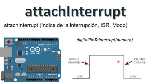
Understanding the attachInterrupt() Syntax on Arduino Uno
To properly use the arduino uno attachinterrupt function, you must understand its syntax and parameters. The function is called within your setup() block to configure the interrupt.
Syntax: attachInterrupt(digitalPinToInterrupt(pin), ISR, mode);
Let’s break down each parameter:
digitalPinToInterrupt(pin): This is the first and most critical parameter. You do not use the raw pin number (e.g.,2). Instead, you must use this macro, which translates the digital pin number to the specific internal interrupt number for that pin.- On the Arduino Uno (and other ATmega328P-based boards), only specific pins can be used for external interrupts. These are digital pin 2 (interrupt 0) and digital pin 3 (interrupt 1). Attempting to use
arduino uno attachinterrupton any other pin will not work.
- On the Arduino Uno (and other ATmega328P-based boards), only specific pins can be used for external interrupts. These are digital pin 2 (interrupt 0) and digital pin 3 (interrupt 1). Attempting to use
ISR(Interrupt Service Routine): This is the name of the function that will be called when the interrupt event occurs. This function must not take any parameters and must not return any value (i.e., its return type isvoid). This is the core piece of code that handles the event. There are strict rules for writing an ISR, which we will cover later.mode: This parameter defines what kind of signal change on the pin will trigger the interrupt. The Arduino Uno supports four modes:LOW: The interrupt is triggered whenever the pin is held at a LOW voltage level. Be cautious with this mode, as the ISR will trigger continuously as long as the pin is LOW.CHANGE: The interrupt is triggered whenever the pin value changes, either from LOW to HIGH or from HIGH to LOW. This is useful for detecting any activity on a pin.RISING: The interrupt is triggered only when the pin’s voltage goes from LOW to HIGH (a rising edge). This is perfect for events like a button being pressed (if wired correctly).FALLING: The interrupt is triggered only when the pin’s voltage goes from HIGH to LOW (a falling edge). This is commonly used for push buttons connected with a pull-up resistor.
A Practical Example: Using arduino uno attachinterrupt for a Push Button
Let’s build a classic example: toggling an LED with a push button. A naive approach would poll the button in the loop(), but we’ll use an interrupt for maximum responsiveness. This example showcases the power of a properly configured arduino uno attachinterrupt.
Hardware Setup:
- Connect an LED to digital pin 13 (the built-in LED on the Uno).
- Connect a push button to digital pin 2. One leg of the button goes to pin 2, and the other leg goes to GND. We will use the internal pull-up resistor.
Code:
// Define the pins
const byte ledPin = 13;
const byte interruptPin = 2;

// This variable will be shared between the ISR and the main loop.
// 'volatile' tells the compiler that this variable can change at any time,
// preventing aggressive optimizations that could lead to bugs.
volatile bool ledState = LOW;

void setup()
  // Initialize the LED pin as an output
  pinMode(ledPin, OUTPUT);

  // Initialize the interrupt pin as an input with an internal pull-up resistor.
  // The pin will be HIGH by default and go LOW when the button is pressed.
  pinMode(interruptPin, INPUT_PULLUP);

  // Attach the interrupt.
  // We use digitalPinToInterrupt() to get the correct interrupt number for pin 2.
  // The ISR to call is 'handleButtonPress'.
  // The trigger mode is FALLING, since pressing the button will pull the pin from HIGH to LOW.
  // This is the core of the arduino uno attachinterrupt implementation.
  attachInterrupt(digitalPinToInterrupt(interruptPin), handleButtonPress, FALLING);

  // You can have other setup code here.
  Serial.begin(9600);
  Serial.println("System ready. Press the button to toggle the LED.");


void loop()
  // The main loop is now free to do other things!
  // For this example, it does nothing, but in a real project,
  // this is where you would put your main application logic.
  // The LED toggling is handled entirely by the interrupt.

  // We just update the physical LED to match our state variable.
  digitalWrite(ledPin, ledState);


// This is the Interrupt Service Routine (ISR)
void handleButtonPress()
  // Toggle the state of the LED
  ledState = !ledState;
Code Explanation:
volatile bool ledState: Thevolatilekeyword is crucial. It tells the compiler that the value ofledStatecan be changed by something outside of the normal program flow (in this case, the ISR). Withoutvolatile, the compiler might optimize the code in theloop()function in a way that assumesledStatenever changes, leading to the program not working as expected.pinMode(interruptPin, INPUT_PULLUP): We use the internal pull-up resistor. This means pin 2 is held at 5V (HIGH) by default. When the button is pressed, it connects the pin to GND, pulling the voltage to 0V (LOW).attachInterrupt(...): Insetup(), we configure ourarduino uno attachinterrupt. We specify pin 2, the ISR functionhandleButtonPress, and theFALLINGmode, which perfectly matches our hardware setup.loop(): Notice how clean theloop()function is. It simply ensures the LED’s physical state matches ourledStatevariable. It’s not busy checking the button. It could be performing complex calculations, communicating over serial, or controlling motors, and it would still respond instantly to the button press.handleButtonPress(): This is our ISR. It’s extremely short and fast, which is a key principle of good ISR design. It does one simple thing: it flips the boolean value ofledState.
Best Practices and Common Pitfalls
While arduino uno attachinterrupt is incredibly useful, it must be used correctly to avoid hard-to-debug issues.
Best Practices
- Keep ISRs Short and Fast: An ISR should execute as quickly as possible. While an ISR is running, all other interrupts are disabled by default. A long ISR can cause other important events (like receiving serial data or timer updates) to be missed. A good pattern is to have the ISR set a flag (a
volatilevariable) and have the mainloop()check for that flag and then perform the longer task. - Use
volatilefor Shared Variables: As demonstrated, any global variable modified within an ISR and also used in the main loop must be declared with thevolatilekeyword. Protect Critical Code Sections: If you are reading or writing a variable that is more than one byte long (e.g.,
int,long,float) and it’s shared with an ISR, you should temporarily disable interrupts during the access in the main loop. This prevents the ISR from firing mid-operation and corrupting the data. This is called an "atomic" operation.// Example of protecting a multi-byte variable long mySharedValue; void loop() noInterrupts(); // Disable interrupts long tempValue = mySharedValue; // Safely copy the value interrupts(); // Re-enable interrupts // Now use tempValue for your calculations
Common Pitfalls
- Using
delay()orSerial.print()in an ISR: This is the most common mistake. Functions likedelay()and most serial communication libraries rely on interrupts themselves. Calling them from within an ISR will cause your program to hang or behave erratically. Thearduino uno attachinterruptcontext cannot handle these functions. - Forgetting
digitalPinToInterrupt(): Simply passing the pin number2toattachInterrupt()will not work. You must use thedigitalPinToInterrupt(2)macro. - Button Bouncing: Mechanical buttons don’t create a clean electrical signal when pressed. They "bounce," creating multiple rapid HIGH/LOW transitions. With a
FALLINGorCHANGEmode, this can cause your ISR to trigger many times for a single physical press. This is not a flaw in thearduino uno attachinterruptsystem but a physical property of buttons. Solutions include:- Hardware Debouncing: A simple RC (resistor-capacitor) circuit can smooth out the signal.
- Software Debouncing: A common technique is to record the time of the last interrupt using
millis()and ignore any subsequent interrupts that occur too quickly. Note that this logic should be handled carefully, asmillis()itself relies on an interrupt and its value won’t update inside an ISR. A better approach is to record the time in the ISR and do the debouncing logic in the main loop.
Advanced Concepts: Detaching and Managing Interrupts
Sometimes you need to dynamically control your interrupts.
detachInterrupt(digitalPinToInterrupt(pin)): This function does the opposite ofattachInterrupt(). It disables the external interrupt on the specified pin. This is useful if you only need to listen for an event during a specific phase of your program’s operation.noInterrupts()andinterrupts(): These functions give you fine-grained control.noInterrupts()disables all interrupts globally, allowing you to execute a "critical section" of code without being interrupted.interrupts()re-enables them. These should be used sparingly and for very short periods, as they can affect the timing of your entire program.
By mastering the arduino uno attachinterrupt function, you unlock a new level of capability for your projects. You move beyond simple, sequential programming into the world of event-driven, real-time control, enabling you to build more sophisticated, responsive, and efficient applications with your Arduino Uno.