Mastering the arduino nano attachinterrupt function is a pivotal step for any enthusiast looking to create more responsive and efficient projects. In the world of microcontrollers, timing is everything. Often, projects require the Arduino to react instantly to an external event, such as a button press, a sensor detecting motion, or a signal from another device. The traditional method of constantly checking the state of a pin inside the main loop() function, a technique known as polling, can be inefficient and may cause the microcontroller to miss brief but critical events. This is where interrupts come into play. An interrupt is a hardware-level signal that tells the processor to immediately stop what it’s doing, execute a special piece of code, and then return to its previous task. The attachInterrupt() function is the Arduino IDE’s gateway to harnessing this powerful feature, and understanding its application on the popular Arduino Nano is essential for advancing your embedded systems skills. This guide will provide a deep dive into the theory, syntax, and practical application of the arduino nano attachinterrupt function.
Daftar Isi
Understanding the Core Concept: Polling vs. Interrupts
- Smartphones in 2025: A Glimpse into the Future of Mobile Technology
- Projects with Arduino for Beginners
- Mastering Real-Time Responses: A Deep Dive into Arduino Mega attachInterrupt
- Arduino Beginner Projects: Your Gateway to Electronics and Programming
- Mastering Arduino attachInterrupt: A Comprehensive Guide to Real-Time Control
Before diving into the code, it’s crucial to understand the fundamental difference between polling and an interrupt-driven approach. This conceptual understanding forms the basis for why arduino nano attachinterrupt is so powerful.
Polling: Imagine you are expecting an important package. The polling method is like going to your front door every two minutes to check if the delivery person has arrived. You spend most of your time and energy just checking, and you can’t do anything else productively. If the delivery person arrives and leaves in the one-minute interval between your checks, you’ll miss the delivery entirely. In Arduino terms, this is what happens in the
loop():
void loop()
  // Can't do much else while constantly checking
  if (digitalRead(buttonPin) == HIGH)
    // Do something
This method is simple but has significant drawbacks. It consumes CPU cycles and can easily miss fast events.
Interrupts: Now, imagine you have a doorbell. You can go about your day—reading a book, cooking, or working—and you don’t think about the package at all. When the delivery person arrives and rings the doorbell, you are immediately notified. You stop what you’re doing, answer the door, and then resume your activity. This is precisely how an interrupt works. The microcontroller can execute its main code in the
loop()function, and when an external event occurs on a specific pin, the hardware automatically pauses the loop and executes a dedicated function called an Interrupt Service Routine (ISR). Once the ISR is complete, theloop()resumes exactly where it left off. The arduino nano attachinterrupt function is what "connects the doorbell" to a specific action.

The primary benefits of using interrupts are:
- Responsiveness: The microcontroller can react to events almost instantaneously, which is critical for time-sensitive applications like motor control or data reception.
- Efficiency: The CPU isn’t wasted on continuously checking pin states. It can perform other complex tasks in the main loop, making your program more powerful and capable.
- Simpler Code Logic: It can simplify the structure of your main loop, as you don’t need to clutter it with constant
ifchecks for various inputs.
The attachInterrupt() Syntax and Parameters
The arduino attachinterrupt function is the key to setting up this behavior. Its syntax is standardized across most Arduino boards, but the available pins can differ.
attachInterrupt(digitalPinToInterrupt(pin), ISR, mode);
Let’s break down each parameter:
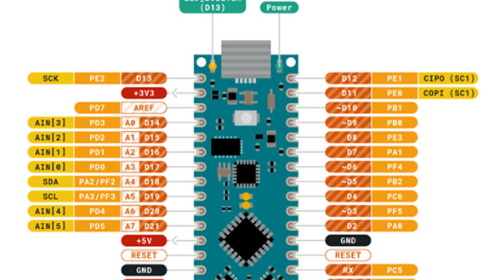
digitalPinToInterrupt(pin): This is not a direct pin number. It’s a special macro that translates a digital pin number (like 2 or 3) into the correct internal interrupt number for the microcontroller. This is a crucial point for the Arduino Nano. The ATmega328P microcontroller on the Nano only supports external interrupts on two specific pins:- Digital Pin 2 (Interrupt 0)
- Digital Pin 3 (Interrupt 1)
You must use one of these two pins for your arduino nano attachinterrupt setup. Trying to use another pin will result in your code compiling but the interrupt never firing.
ISR(Interrupt Service Routine): This is the name of the function that will be executed when the interrupt is triggered. This function must not take any arguments and must not return any value (i.e., its return type isvoid). For example,void myButtonFunction(). We will discuss the rules for writing a proper ISR later, as they are very important.mode: This parameter defines what kind of signal change on the pin will trigger the interrupt. There are four possible modes:LOW: The interrupt is triggered whenever the pin is at a LOW voltage level. Be cautious with this mode, as the ISR will be called continuously as long as the pin is held LOW.CHANGE: The interrupt is triggered whenever the pin’s value changes, either from LOW to HIGH or from HIGH to LOW.RISING: The interrupt is triggered only when the pin’s voltage goes from LOW to HIGH (a rising edge). This is very common for button presses where you want to detect the moment the button is pushed.FALLING: The interrupt is triggered only when the pin’s voltage goes from HIGH to LOW (a falling edge). This is often used for button releases or with sensors that pull a pin low to signal an event.
Practical Implementation: A Step-by-Step arduino nano attachinterrupt Example
Let’s build a simple but effective circuit to demonstrate the power of the arduino nano attachinterrupt function. We will have an LED that blinks at a regular interval, controlled by the main loop(). Separately, we will have a pushbutton that, when pressed, will instantly toggle the state of a second LED, without interrupting the blinking of the first one.
Hardware Required:
- Arduino Nano
- 2 x LEDs (e.g., one red, one green)
- 2 x 220Ω resistors (for the LEDs)
- 1 x Pushbutton
- 1 x 10kΩ resistor (for the pulldown)
- Breadboard and jumper wires
Circuit Setup:
- Connect the first LED (blinking) to Digital Pin 8 via a 220Ω resistor.
- Connect the second LED (interrupt-controlled) to Digital Pin 7 via a 220Ω resistor.
- Connect one leg of the pushbutton to the 5V pin on the Nano.
- Connect the other leg of the pushbutton to Digital Pin 2 on the Nano.
- Connect that same leg of the pushbutton to GND via the 10kΩ pulldown resistor. This ensures that when the button is not pressed, Pin 2 is held LOW. When pressed, it goes HIGH.
The Code:
// Define pin numbers for clarity
const int blinkLedPin = 8;
const int interruptLedPin = 7;
const int buttonPin = 2; // Must be 2 or 3 for Nano external interrupts

// This variable is shared between the ISR and the main loop
// 'volatile' tells the compiler that this variable can change at any time
// unexpectedly, so it should always be read from memory, not a cache.
volatile bool interruptLedState = LOW;

// The Interrupt Service Routine (ISR)
// This function is called when the button is pressed.
// Keep ISRs as short and fast as possible!
void handleButtonPress()
  interruptLedState = !interruptLedState; // Toggle the state


void setup()
  // Set pin modes
  pinMode(blinkLedPin, OUTPUT);
  pinMode(interruptLedPin, OUTPUT);
  pinMode(buttonPin, INPUT); // Button pin is an input

  // This is the core of our arduino nano attachinterrupt setup.
  // We are attaching an interrupt to Pin 2.
  // The interrupt will trigger the 'handleButtonPress' function
  // on a RISING edge (when the button is pressed and the pin goes from LOW to HIGH).
  attachInterrupt(digitalPinToInterrupt(buttonPin), handleButtonPress, RISING);


void loop()
  // --- Main Program Task ---
  // This part of the code runs independently of the interrupt.
  // It simply blinks the first LED every second.
  digitalWrite(blinkLedPin, HIGH);
  delay(500);
  digitalWrite(blinkLedPin, LOW);
  delay(500);

  // --- Handling the Interrupt Flag ---
  // The ISR only set a flag (changed the state of 'interruptLedState').
  // The main loop acts on that flag. This is a good practice.
  digitalWrite(interruptLedPin, interruptLedState);
How It Works:
- In
setup(), we configure the pin modes and then make the crucial arduino nano attachinterrupt call. This tells the Nano to constantly monitor Pin 2 for a RISING edge. - The
loop()function carries on with its primary task: blinking the LED on Pin 8. It is completely unaware of the button. It also checks theinterruptLedStatevariable on every iteration and sets the second LED accordingly. - When you press the button, the voltage on Pin 2 goes from LOW to HIGH. The ATmega328P hardware detects this rising edge and immediately pauses the
loop()(wherever it might be, even inside adelay()). - It then jumps to and executes the
handleButtonPress()ISR. This function is extremely fast; it just flips the boolean value ofinterruptLedState. - After the ISR is finished, the
loop()function resumes exactly where it was interrupted. - On its next pass, the
loop()will see the new value ofinterruptLedStateand update the LED on Pin 7. The result is an instant response from the second LED, while the first LED’s blinking rhythm remains undisturbed.
Best Practices and Important Rules for ISRs
Writing an Interrupt Service Routine is not like writing a regular function. Because they can interrupt any part of your code at any time, there are strict rules to follow for a stable arduino nano attachinterrupt implementation.
- Keep ISRs Short and Fast: An ISR should do the absolute minimum work required. A common and highly recommended practice is to have the ISR set a flag (like in our example) or update a variable, and then let the main
loop()handle the more complex logic based on that flag. - Use
volatilefor Shared Variables: Any global variable that is modified within an ISR and also used in the mainloop()must be declared with thevolatilekeyword. This prevents the compiler from making optimizations that could lead to your main loop using a stale, cached value of the variable, since the compiler doesn’t normally expect a variable to change on its own. The successful use of arduino nano attachinterrupt often depends on the correct use ofvolatile. - Avoid
delay()andSerialFunctions: Functions likedelay()anddelayMicroseconds()rely on timers that are themselves interrupt-driven. Using them inside an ISR can cause your program to freeze or behave erratically. Similarly,Serial.print()and other serial communication functions are slow and can be unreliable inside an ISR. If you need to debug, set a flag in the ISR and do the printing from the main loop. - Be Careful with
millis()andmicros(): While these functions can sometimes work inside an ISR, they will not increment while the ISR is running. This can lead to inaccurate timing if your ISR takes too long to execute. - Atomic Access: When dealing with variables larger than a single byte (like
int,long, orfloat) that are shared between an ISR and the main loop, you can run into a problem where the ISR fires in the middle of the main loop reading or writing the variable. This can corrupt the data. To prevent this, you should disable interrupts temporarily while accessing the variable in the main loop.// Example of safe access to a multi-byte variable noInterrupts(); // Disable all interrupts long myValue = sharedCounter; // Safely copy the value interrupts(); // Re-enable interrupts
Troubleshooting Common arduino nano attachinterrupt Issues
- Interrupt Not Firing:
- Wrong Pin: Double-check that you are using Pin 2 or Pin 3 on your Arduino Nano.
- Wiring Issue: Ensure your button is wired correctly with a pulldown or pullup resistor to prevent a "floating" pin state.
- Wrong Mode: Make sure your
mode(RISING,FALLING, etc.) matches the electrical behavior of your circuit.
- Multiple Triggers from a Single Press (Bouncing):
- Mechanical buttons don’t close cleanly; they "bounce" on a microsecond scale, creating multiple rapid rising and falling edges. This can cause your ISR to fire many times for a single press.
- Software Debouncing: A common solution is to record the time of the last interrupt using
millis()and ignore any subsequent interrupts that occur too quickly. Note that this logic must be implemented inside the ISR. - Hardware Debouncing: A small capacitor (e.g., 0.1µF) across the switch can help smooth out the signal and physically eliminate the bounce.
By understanding the principles, syntax, and best practices, you can effectively use the arduino nano attachinterrupt function to create projects that are faster, more efficient, and more reliable. It is a fundamental technique that unlocks a more advanced and professional level of microcontroller programming.