Understanding how to properly use the Arduino Mega attachInterrupt function is a cornerstone of advanced microcontroller programming, enabling your projects to react to external events with near-instantaneous speed and efficiency. In the standard Arduino workflow, the processor executes code sequentially within the loop() function. This method, often called polling, involves constantly checking the state of a sensor or pin to see if an event has occurred. While simple, polling is inefficient. The microcontroller wastes countless CPU cycles checking for an event that may happen infrequently, preventing it from performing other tasks. Interrupts provide an elegant solution to this problem, allowing the microcontroller to pause its current task, handle an urgent event, and then resume exactly where it left off.
This article will serve as a comprehensive guide to using interrupts on the Arduino Mega. We will explore the fundamental concepts behind interrupts, break down the syntax of the attachInterrupt() function, highlight the specific advantages of the Mega’s hardware, and provide practical code examples and best practices to help you build more responsive and powerful projects. By mastering the Arduino Mega attachInterrupt system, you unlock the ability to handle time-sensitive tasks like reading rotary encoders, monitoring emergency stop buttons, or capturing high-frequency signals without bogging down your main program.
- Projects with Arduino for Beginners
- Arduino Beginner Projects: Your Gateway to Electronics and Programming
- Arduino Based Projects for Beginners
- Mastering Arduino attachInterrupt: A Comprehensive Guide to Real-Time Control
- Smartphones in 2025: A Glimpse into the Future of Mobile Technology
Daftar Isi
What Are Interrupts and Why Are They Essential?
An interrupt is a signal to the processor emitted by hardware or software, indicating an event that needs immediate attention. Think of it like a doorbell. You could spend your entire day repeatedly opening the door to check if a visitor has arrived (polling), or you can go about your business and only respond when the doorbell rings (interrupt). The interrupt-driven approach is far more efficient.
In the context of Arduino, we are primarily concerned with hardware interrupts. These are triggered by a change in the electrical state of a specific pin on the microcontroller. When the configured event occurs—such as a voltage changing from LOW to HIGH—the microcontroller automatically performs the following steps:
- It finishes the current instruction it is executing.
- It saves its current state (the values in its registers) to a specific place in memory.
- It jumps to a special function called an Interrupt Service Routine (ISR) that you have written.
- It executes the code within the ISR.
- Once the ISR is complete, it restores its previous state from memory and resumes executing the main code from the exact point it was interrupted.

This entire process happens in hardware and is incredibly fast. The benefits of using an Arduino Mega attachInterrupt approach over polling are significant:
- Improved Responsiveness: Your program can react to events in microseconds, which is crucial for applications requiring real-time control. A polled button press might be missed if the
loop()is busy with a longdelay()or a complex calculation. An interrupt will catch it every time. - CPU Efficiency: The processor is free to perform other tasks, like updating a display, communicating over Serial, or performing calculations, instead of being stuck in a tight loop checking a pin’s status. This allows for more complex and multi-faceted projects.
- Handling Asynchronous Events: Interrupts are perfect for dealing with events that don’t happen in a predictable sequence, such as user input, sensor triggers, or data arriving from another device.
- Simplified Code Structure: While the initial setup for an Arduino Mega attachInterrupt might seem complex, it can often lead to a cleaner main
loop(). The event-handling logic is neatly encapsulated within the ISR, leaving theloop()to manage the program’s main state.
The attachInterrupt() Function Explained
The core of the Arduino interrupt system is the attachInterrupt() function. This function tells the microcontroller which pin to monitor, what function to run when an interrupt occurs, and what kind of event should trigger it.
The syntax is as follows:
attachInterrupt(digitalPinToInterrupt(pin), ISR, mode);
Let’s break down each parameter:
1. digitalPinToInterrupt(pin)
This is a critical and often misunderstood part of the function. You do not use the physical pin number directly. Instead, you use this macro to translate the digital pin number into its corresponding internal interrupt number. For example, to use digital pin 2, you would write digitalPinToInterrupt(2). This abstraction makes the code more portable across different Arduino boards.
2. ISR (Interrupt Service Routine)
This is the name of the special function you want to execute when the interrupt is triggered. This function must not take any parameters and must not return any value (i.e., its return type is void). For example: void myButtonFunction().
3. mode
This parameter defines what specific electrical event on the pin will trigger the interrupt. There are four options:
LOW: The interrupt is triggered whenever the pin is at a LOW voltage level. Be cautious with this mode, as the ISR will be triggered continuously as long as the pin is held LOW.CHANGE: The interrupt is triggered whenever the pin’s value changes, either from LOW to HIGH or from HIGH to LOW. This is useful for monitoring state changes.RISING: The interrupt is triggered only when the pin’s voltage goes from LOW to HIGH. This is ideal for events like a button press in a pull-down configuration.FALLING: The interrupt is triggered only when the pin’s voltage goes from HIGH to LOW. This is perfect for a button press in a pull-up configuration.
A proper implementation of the Arduino Mega attachInterrupt function is foundational to a stable system.
Interrupts on the Arduino Mega: The Hardware Advantage
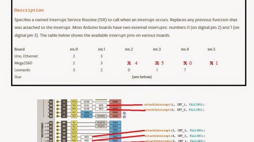
While the concepts of interrupts apply to all Arduino boards, the Arduino Mega 2560 has a significant advantage over its smaller cousins like the Uno: it has more dedicated external interrupt pins.
- Arduino Uno: Has only two external interrupt pins: Pin 2 (interrupt 0) and Pin 3 (interrupt 1).
- Arduino Mega 2560: Has six external interrupt pins, providing much more flexibility for complex projects.
Here is the mapping for the Arduino Mega:
| Digital Pin | Interrupt Number |
|---|---|
| 2 | 0 |
| 3 | 1 |
| 21 | 2 |
| 20 | 3 |
| 19 | 4 |
| 18 | 5 |
This expanded capability of the Arduino Mega attachInterrupt system means you can simultaneously monitor up to six different high-priority external signals without resorting to more complex methods like pin-change interrupts. This makes the Mega an excellent choice for projects involving multiple rotary encoders, motor feedback sensors, or various user input buttons that all require immediate attention. The process of setting up an Arduino Mega attachInterrupt on pin 18 is identical to setting one up on pin 2; you simply change the pin number inside the digitalPinToInterrupt() macro.
Practical Example: A Responsive LED Toggle with a Button
Let’s build a simple circuit to demonstrate the power of the Arduino Mega attachInterrupt. We will use a pushbutton to toggle an LED. Unlike a polled example where a delay() in the main loop could cause a missed press, this version will be perfectly responsive.
Hardware Required:
- Arduino Mega 2560
- An LED
- A 220Ω resistor (for the LED)
- A momentary pushbutton
- A 10kΩ resistor (for the button)
- Breadboard and jumper wires
Circuit (Pull-down configuration):
- Connect Arduino’s 5V pin to one leg of the pushbutton.
- Connect the other leg of the pushbutton to the Arduino Mega’s Digital Pin 2.
- Connect a 10kΩ resistor from that same leg (Digital Pin 2) to the Arduino’s GND.
- Connect the long leg (anode) of the LED to a 220Ω resistor.
- Connect the other end of the resistor to the Arduino Mega’s Digital Pin 13.
- Connect the short leg (cathode) of the LED to the Arduino’s GND.
The Code:
// Define the pins we are using
const byte ledPin = 13;
const byte interruptPin = 2;

// This variable will be shared between the ISR and the main loop.
// 'volatile' tells the compiler that its value can change at any time
// due to external factors (like an interrupt).
volatile bool ledState = LOW;

void setup()
  // Set the LED pin as an output
  pinMode(ledPin, OUTPUT);

  // Set the interrupt pin as an input. With a pull-down resistor,
  // it will be LOW when the button is not pressed.
  pinMode(interruptPin, INPUT);

  // In this setup, the core of the Arduino Mega attachInterrupt is configured.
  // We attach an interrupt to pin 2.
  // The ISR to call is named 'handleButtonPress'.
  // The interrupt will trigger on a RISING edge (when the button is pressed,
  // the pin goes from LOW to HIGH).
  attachInterrupt(digitalPinToInterrupt(interruptPin), handleButtonPress, RISING);

  Serial.begin(9600);
  Serial.println("Interrupt system initialized. Press the button.");


void loop()
  // The main loop is now very clean.
  // It simply checks the state variable and updates the LED.
  // It could be doing many other things here without affecting
  // the responsiveness of the button.
  digitalWrite(ledPin, ledState);


// This is the Interrupt Service Routine (ISR)
void handleButtonPress()
  // Toggle the state of the LED
  ledState = !ledState;
Explanation:
When you press the button, the voltage on pin 2 goes from LOW to HIGH, triggering the RISING edge interrupt. The Arduino immediately pauses the loop(), jumps to the handleButtonPress() function, flips the value of ledState, and then resumes the loop(). The loop() then sees the new value of ledState on its next iteration and updates the physical LED. The use of volatile is crucial; it prevents the compiler from making optimizations that might cause it to miss the change in the ledState variable made by the ISR. This example is a perfect illustration of a robust Arduino Mega attachInterrupt implementation.
Best Practices and Advanced Considerations
While using arduino attachinterrupt is powerful, there are important rules and considerations to ensure your program remains stable.
Keep ISRs Short and Fast: An ISR should execute as quickly as possible. While an ISR is running, most other interrupts are disabled. If your ISR takes too long, you might miss other important events, and it can disrupt the timing of functions like
millis()andmicros(). Do the absolute minimum work necessary inside the ISR—often just setting a flag or updating a variable—and let the mainloop()handle the rest. The successful use of Arduino Mega attachInterrupt depends on efficient ISR design.Avoid
delay()and Serial Communication in ISRs: Functions likedelay()andSerial.print()rely on interrupts themselves to work. Since interrupts are disabled inside an ISR, these functions will not behave as expected and can cause your program to hang. If you need to debug, set a flag in the ISR and do theSerial.print()from the mainloop().Use
volatilefor Shared Variables: Any global variable that is modified within an ISR and also accessed in the main loop must be declared with thevolatilekeyword. This ensures the compiler fetches the variable’s value from RAM every time it’s accessed, rather than using a potentially outdated value stored in a register. This is a non-negotiable rule for any Arduino Mega attachInterrupt configuration.Button Debouncing: Mechanical buttons don’t produce a clean electrical signal when pressed. They "bounce," creating a rapid series of ON-OFF signals for a few milliseconds. An interrupt set to
RISINGorCHANGEwill trigger multiple times for a single button press. This can be solved in two ways:- Hardware: Add a small capacitor and resistor (an RC filter) to the button circuit to smooth out the signal.
- Software: In the ISR, record the time of the interrupt using
millis(). In the main loop or the ISR itself, ignore any subsequent triggers that occur within a short debounce period (e.g., 50ms). A common practice is to record the time in the ISR and do the logic check in theloop().
Atomic Access: When dealing with variables larger than a single byte (like
intorlong) that are shared between an ISR and the main loop, you risk a "race condition." The ISR might modify the variable halfway through the main loop reading it, resulting in corrupted data. To prevent this, you should temporarily disable interrupts while accessing the variable in the main loop, creating a "critical section" or "atomic block."// Example of safely reading a multi-byte volatile variable long myVolatileValue; void loop() long localCopy; noInterrupts(); // Disable interrupts localCopy = myVolatileValue; // Make a copy interrupts(); // Re-enable interrupts // Now use 'localCopy' for your calculations Serial.println(localCopy);
Conclusion
The Arduino Mega attachInterrupt function is a powerful tool that elevates your projects from simple sequential programs to highly responsive, event-driven systems. By offloading the task of monitoring external events to the microcontroller’s dedicated hardware, you free up the CPU to perform more complex tasks, resulting in more efficient and capable applications. While there are important rules to follow, such as keeping ISRs short and using volatile variables, the benefits are immense. With its six external interrupt pins, the Arduino Mega provides ample opportunity to build sophisticated projects that can react to the physical world with precision and speed. Experimenting with a simple Arduino Mega attachInterrupt setup, like the button example, is the first step toward mastering this essential technique and unlocking the full potential of your microcontroller.