The arduino attachinterrupt function is a fundamental tool for creating responsive and efficient microcontroller projects, allowing your code to react instantly to external events without constantly checking for them. In the world of microcontrollers, a program typically runs through a series of instructions sequentially within a main loop. This method, known as polling, involves repeatedly checking the state of a sensor or input. While simple, polling can be inefficient and may miss very fast events. This is where interrupts come in. An interrupt is a signal to the processor that an important event has occurred, causing it to pause its current task, execute a special function to handle the event, and then resume its original task. Using arduino attachinterrupt is like having a dedicated doorbell for your code; instead of constantly looking out the window to see if someone is there (polling), your program can continue its main work until the doorbell rings (the interrupt), at which point it immediately goes to answer the door.
Daftar Isi
- 1 What Are Interrupts and Why Are They Essential?
- 2 The arduino attachinterrupt Syntax Explained
- 3 A Simple arduino attachinterrupt example: Toggling an LED
- 4 Advanced Application: Using attachinterrupt arduino encoder
- 5 Exploring timer1 attachinterrupt arduino: Internal Interrupts
- 6 Best Practices and Common Pitfalls
What Are Interrupts and Why Are They Essential?
- Arduino Beginner Projects: Your Gateway to Electronics and Programming
- NodeMCU
- Projects with Arduino for Beginners
- How to Program an Arduino: A Comprehensive Guide for Beginners
At its core, an interrupt is a hardware-driven mechanism. When a specific event happens on a designated pin—such as a voltage change—the microcontroller’s hardware automatically pauses the main loop() and executes a pre-defined function called an Interrupt Service Routine (ISR). Once the ISR is complete, the main program continues exactly where it left off, often without even knowing it was paused. This interrupt-driven approach provides several significant advantages over traditional polling.
The primary benefits of using the arduino attachinterrupt function include:
- Responsiveness: Interrupts provide near-instantaneous reaction to events. This is critical for applications like emergency stop buttons, object detection sensors on a fast-moving robot, or receiving data from a high-speed device.

- Efficiency: The main processor isn’t wasted on continuously checking pin states. It can perform other complex calculations, update displays, or manage communications, only diverting its attention when absolutely necessary. This frees up valuable processing cycles.
- Accuracy in Counting and Timing: For tasks like measuring the speed of a spinning wheel with an
attachinterrupt arduino encodersetup, interrupts are indispensable. Polling might miss quick pulses, leading to inaccurate readings, but an interrupt will catch every single one. - Simplified Code Logic: Complex state-checking logic within the main
loop()can often be replaced by a clean and simple ISR. This makes the main program easier to read, write, and debug, as the event-handling code is neatly encapsulated.
The arduino attachinterrupt Syntax Explained
To implement this powerful feature, you need to understand its syntax and parameters. The function is typically called within the setup() section of your sketch.
attachInterrupt(digitalPinToInterrupt(pin), ISR, mode);
Let’s break down each component:
1. digitalPinToInterrupt(pin)
This is a crucial first step. You cannot use arduino attachinterrupt on just any digital pin. Each Arduino board has specific pins that are hard-wired to support external interrupts. This function translates the physical pin number (e.g., 2, 3) into the correct internal interrupt number for the microcontroller.
- Arduino UNO, Nano: Pins 2 and 3.
- Arduino Mega 2560: Pins 2, 3, 18, 19, 20, 21.
- Arduino Due, MKR series: All digital pins can be used.
Always consult your board’s documentation to confirm which pins are interrupt-capable. Using a non-interrupt pin will result in your code not working as expected.
2. ISR (Interrupt Service Routine)
This is the name of the function that will be executed when the interrupt is triggered. This function is one you write yourself. There are strict rules for writing an ISR:
- Keep it Short and Fast: An ISR should execute as quickly as possible. While it runs, all other interrupts are paused, and functions like
millis()andmicros()will not update. - No
delay(): Never usedelay()ordelayMicroseconds()inside an ISR. - Limited Serial Communication: Using
Serial.print()inside an ISR can cause your program to crash or behave erratically, as serial communication is itself interrupt-driven. It’s best to set a flag variable inside the ISR and do the printing in the mainloop(). - Declare Shared Variables as
volatile: Any global variable that is modified within an ISR and also used in the main loop must be declared with thevolatilekeyword (e.g.,volatile int counter = 0;). This tells the compiler that the variable’s value can change at any time, preventing it from making optimizations that could lead to bugs.
3. mode
This parameter defines what kind of pin event will trigger the interrupt. There are four primary modes:
LOW: The interrupt is triggered whenever the pin is held at a LOW voltage level. Be cautious with this mode, as the ISR will be triggered continuously as long as the pin is low.CHANGE: The interrupt is triggered whenever the pin value changes, from HIGH to LOW or LOW to HIGH.RISING: The interrupt is triggered only when the pin goes from LOW to HIGH.FALLING: The interrupt is triggered only when the pin goes from HIGH to LOW. This is very common for button presses with a pull-up resistor.
A Simple arduino attachinterrupt example: Toggling an LED
Let’s see the arduino attachinterrupt function in action with a classic example: using a push-button to toggle an LED. This demonstrates how the main loop can be completely empty while the program remains fully responsive.
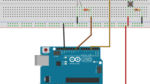
Hardware Setup:
- Connect an LED to pin 13 (or another digital pin with a current-limiting resistor).
- Connect a push-button to pin 2. Connect the other side of the button to GND. We will use the internal pull-up resistor.
Code:
// Pin definitions
const byte ledPin = 13;
const byte interruptPin = 2;

// Volatile variable to store the LED state
// It is shared between the ISR and the main loop
volatile bool ledState = LOW;

void setup()
  // Set the LED pin as an output
  pinMode(ledPin, OUTPUT);

  // Set the interrupt pin as an input with an internal pull-up resistor
  // The pin will be HIGH by default and go LOW when the button is pressed
  pinMode(interruptPin, INPUT_PULLUP);

  // Attach the interrupt to the pin.
  // The arduino attachinterrupt function is configured here.
  // It will call the function "handleButtonPress" on a FALLING edge
  attachInterrupt(digitalPinToInterrupt(interruptPin), handleButtonPress, FALLING);


void loop()
  // The main loop can do other things, or nothing at all.
  // We just update the physical LED to match our state variable.
  digitalWrite(ledPin, ledState);


// The Interrupt Service Routine (ISR)
// This function must be short and fast.
void handleButtonPress()
  // Toggle the LED state
  ledState = !ledState;
In this arduino attachinterrupt example, when you press the button, the voltage on pin 2 falls from HIGH to LOW, triggering the interrupt. The handleButtonPress ISR is immediately called, which flips the ledState variable. The main loop() simply ensures the physical LED reflects the current state.
Advanced Application: Using attachinterrupt arduino encoder
Rotary encoders are devices used for precise rotational input, common in volume knobs and CNC machine controls. They output two signals (A and B) that are out of phase. By monitoring which signal changes first, we can determine the direction of rotation. The arduino attachinterrupt function is perfect for this, as it can catch the very fast signal changes from a spinning encoder.
Code Example:
#define ENCODER_PIN_A 2
#define ENCODER_PIN_B 3

// Volatile variable for the encoder count
volatile long encoderCount = 0;

void setup()
  Serial.begin(9600);

  pinMode(ENCODER_PIN_A, INPUT_PULLUP);
  pinMode(ENCODER_PIN_B, INPUT_PULLUP);

  // Set up the arduino attachinterrupt for pin A
  attachInterrupt(digitalPinToInterrupt(ENCODER_PIN_A), readEncoder, CHANGE);
  // Set up the arduino attachinterrupt for pin B
  attachInterrupt(digitalPinToInterrupt(ENCODER_PIN_B), readEncoder, CHANGE);

  Serial.println("Encoder ready. Start turning.");


void loop()
  // The main loop only prints the value when it changes
  static long lastEncoderCount = 0;
  if (encoderCount != lastEncoderCount)
    Serial.print("Position: ");
    Serial.println(encoderCount);
    lastEncoderCount = encoderCount;


// ISR to read the encoder
void readEncoder()
  // Simple quadrature logic
  static int8_t lastStateA = 0;
  int8_t stateA = digitalRead(ENCODER_PIN_A);

  if (stateA != lastStateA)  // A has changed
    if (digitalRead(ENCODER_PIN_B) != stateA)
      encoderCount++; // Clockwise
     else
      encoderCount--; // Counter-clockwise


  lastStateA = stateA;
This attachinterrupt arduino encoder example uses two interrupts, one for each encoder pin, both triggering on CHANGE. The readEncoder ISR implements a simple quadrature decoding logic to increment or decrement a counter, accurately tracking the encoder’s position. The use of arduino attachinterrupt ensures no steps are missed, even at high speeds.
Exploring timer1 attachinterrupt arduino: Internal Interrupts
So far, we have discussed external interrupts triggered by pin changes. However, Arduinos also have internal interrupts triggered by timers. These are incredibly useful for performing tasks at precise, regular intervals without blocking the main loop, unlike delay(). While you can manipulate timer registers directly, a popular and easy way to get started is with the TimerOne library.
Let’s use timer1 attachinterrupt arduino to blink an LED every 500 milliseconds without using delay().
Code using TimerOne Library:
First, install the “TimerOne” library from the Arduino Library Manager.
#include <TimerOne.h>

const byte ledPin = 13;

void setup()
  pinMode(ledPin, OUTPUT);

  // Initialize Timer1
  Timer1.initialize(500000); // Initialize for 500,000 microseconds (0.5 seconds)

  // Attach the ISR function "blinkLed" to the timer interrupt
  Timer1.attachInterrupt(blinkLed);

  Serial.begin(9600);
  Serial.println("Timer interrupt started. LED will blink every 0.5s.");


void loop()
  // This loop is completely free to do other tasks!
  // For example, we can print a message every second.
  Serial.println("Main loop is running...");
  delay(1000); // Using delay here doesn't affect the timer-based blink!


// The ISR for the timer interrupt
void blinkLed()
  digitalWrite(ledPin, !digitalRead(ledPin)); // Toggle the LED
In this example, the Timer1.attachInterrupt(blinkLed) line sets up an internal interrupt. The blinkLed function is now called automatically by the hardware every 500ms, completely independent of the main loop(). This demonstrates a form of simple multitasking and is a far more robust approach to timing than using delay(). This powerful technique is a core part of many advanced projects. The arduino attachinterrupt function is for external events, while libraries like TimerOne provide an easy interface for internal timer interrupts.
Best Practices and Common Pitfalls
To effectively use arduino attachinterrupt, keep these points in mind:
- Best Practices:
- Keep ISRs Lean: An ISR should only do the absolute minimum work required, such as setting a flag or updating a counter. Offload any heavy processing to the main
loop(). - Use
volatile: Always use thevolatilekeyword for variables shared between an ISR and the main program. - Debounce Switches: Mechanical buttons can “bounce,” creating multiple rapid signals from a single press. This can cause your ISR to trigger many times. Implement software or hardware debouncing to solve this.
- Critical Sections: If you need to read a multi-byte variable (like a
long) that is modified by an ISR, you should temporarily disable interrupts while reading it to prevent data corruption. UsenoInterrupts()before reading andinterrupts()after.
- Keep ISRs Lean: An ISR should only do the absolute minimum work required, such as setting a flag or updating a counter. Offload any heavy processing to the main
- Common Pitfalls:
- Long-running code in ISR: The most common mistake is putting
delay(),Serial.print(), or complex loops inside an ISR. This will hang your program. - Forgetting
volatile: This can lead to very strange and hard-to-diagnose bugs where the main loop doesn’t see the updated value from the ISR. - Using the wrong pins: Double-check your board’s documentation to ensure you are using a pin that supports
arduino attachinterrupt. - Race Conditions: Be mindful of situations where the interrupt could occur in the middle of a critical operation in your main loop, leading to unpredictable behavior.
- Long-running code in ISR: The most common mistake is putting
In conclusion, the arduino attachinterrupt function is a gateway to writing more professional, responsive, and efficient code. By understanding how to offload event detection from the main loop to the microcontroller’s hardware, you can build projects that handle high-speed inputs, react instantly to user interaction, and perform multiple tasks with greater precision and reliability. From a simple button press to reading a complex attachinterrupt arduino encoder or using a timer1 attachinterrupt arduino setup for precise timing, mastering interrupts is a key skill for any serious Arduino developer.