Understanding how to effectively use attachinterrupt attiny85 is a fundamental skill for anyone looking to create responsive, power-efficient, and sophisticated projects with this compact yet powerful microcontroller. While the ATtiny85 is celebrated for its small footprint and low power consumption, its limited processing power means that efficient code is not just a preference—it’s a necessity. Interrupts provide a powerful mechanism to handle events asynchronously, allowing the microcontroller to perform other tasks or enter low-power sleep modes instead of wasting cycles continuously checking for input. This guide will delve deep into the theory, syntax, and practical application of interrupts on the ATtiny85, transforming your projects from basic to brilliant.
Daftar Isi
What Are Interrupts and Why Are They Crucial for the ATtiny85?
- Mastering Arduino attachInterrupt: A Comprehensive Guide to Real-Time Control
- Smartphones in 2025: A Glimpse into the Future of Mobile Technology
- Projects with Arduino for Beginners
- Arduino Beginner Projects: Your Gateway to Electronics and Programming
- Mastering Real-Time Responses: A Deep Dive into Arduino Mega attachInterrupt
At its core, an interrupt is a signal to the processor that an event of immediate importance has occurred. When an interrupt is triggered, the microcontroller immediately pauses its current task in the main loop(), executes a special function called an Interrupt Service Routine (ISR), and then resumes the main loop exactly where it left off.
To understand the value of this, consider the alternative: polling. Polling is the process of repeatedly checking the status of a pin or sensor inside the main loop().
 Polling Example: Imagine you want to detect a button press. With polling, your
 loop()would look something like this:void loop() if (digitalRead(buttonPin) == LOW) // Do something when button is pressed // Do other thingsThe problem here is that the microcontroller spends a significant amount of time just checking the button’s state. If the “other things” in your loop take a long time to execute, you might miss a quick button press entirely. Furthermore, the CPU is always active, consuming power.
- Interrupt Example: With an interrupt, you tell the microcontroller, “Hey, let me know only when the state of this pin changes.” The main
loop()can be completely empty or busy with other tasks. When the button is pressed, the hardware automatically triggers the ISR.
 Polling Example: Imagine you want to detect a button press. With polling, your
 The benefits for a resource-constrained chip like the ATtiny85 are immense:
- Responsiveness: Events like button presses, sensor triggers, or data signals are handled instantly, without any delay caused by other code in the main loop.
- Efficiency: The CPU isn’t wasted on constant checking. It’s free to perform complex calculations, manage animations, or handle other logic, knowing that critical events will be caught.
- Power Savings: This is perhaps the biggest advantage for ATtiny85 projects, many of which are battery-powered. By using interrupts, the microcontroller can be put into a deep sleep mode, consuming microamps of power. It will only wake up when an interrupt event occurs, perform its task, and go back to sleep. This can extend battery life from days to months or even years. The proper implementation of
attachinterrupt attiny85is key to unlocking this capability.
The ATtiny85 Pinout and Interrupt Capabilities
Before we can use attachinterrupt, we must understand which pins on the ATtiny85 support it. This is a critical point where the ATtiny85 differs significantly from larger Arduino boards like the Uno.
The standard arduino attachinterrupt function is designed for external interrupts. The ATtiny85 has only one dedicated external interrupt pin.
- External Interrupt (INT0): This is available on PB2 (Physical Pin 7). This is the only pin that can be used directly with the
attachInterrupt()function in the standard Arduino environment.
What if you need to monitor other pins? The ATtiny85 offers another powerful feature: Pin Change Interrupts (PCINT). All I/O pins (PB0 to PB5) are capable of triggering a pin change interrupt. However, these are handled differently. All pins in a group trigger the same ISR, and it’s up to your code to figure out which specific pin changed. While powerful, this is more complex than using the dedicated INT0. For the purpose of this guide, we will focus on the simpler and more common attachinterrupt attiny85 implementation using the INT0 pin.
The attachInterrupt() Syntax for the ATtiny85
The syntax for setting up an interrupt is standardized across the Arduino framework, but its application to the ATtiny85 has specific nuances. The function requires three arguments:
attachInterrupt(digitalPinToInterrupt(pin), ISR, mode);
Let’s break down each parameter in the context of the ATtiny85:
digitalPinToInterrupt(pin): This is a macro that translates a digital pin number to the correct internal interrupt number. For the ATtiny85, the external interrupt pin is PB2. In most ATtiny85 core libraries for Arduino, this corresponds to digital pin 2. Therefore, you will usedigitalPinToInterrupt(2). This will resolve to interrupt number 0 (for INT0). Using this macro makes your code more portable and readable.ISR(Interrupt Service Routine): This is the name of the function you want to execute when the interrupt is triggered. This function must not take any arguments and must not return any value (i.e., its return type isvoid). For example, a function namedhandleButtonPress.mode: This defines what kind of action on the pin will trigger the interrupt. There are four possible modes:LOW: The interrupt is triggered continuously as long as the pin is held low. This is useful for level-triggered events but can be tricky as the ISR will fire repeatedly.CHANGE: The interrupt is triggered whenever the pin changes value, from high to low or low to high.RISING: The interrupt is triggered only when the pin goes from low to high.FALLING: The interrupt is triggered only when the pin goes from high to low. This is the most common mode for handling button presses with a pull-up resistor.
A proper call to attachinterrupt attiny85 might look like this:
attachInterrupt(digitalPinToInterrupt(2), myISR, FALLING);
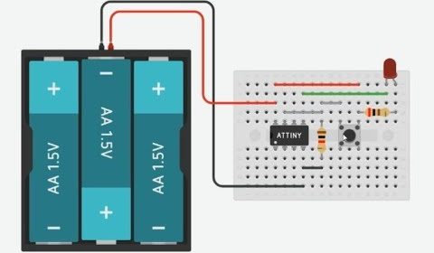
Practical Example: A Button-Controlled LED
Let’s solidify this knowledge with a complete, working example. We will create a simple circuit where pressing a button toggles an LED on and off. The main loop() will be empty to demonstrate that all the action is handled by the interrupt. This is a classic demonstration of the power of the attachinterrupt attiny85 function.
Hardware Required:
- ATtiny85
- 1x LED
- 1x 220Ω resistor (for the LED)
- 1x Pushbutton
- Breadboard and jumper wires
Circuit Diagram:
- LED Anode (+) to PB0 (Physical Pin 5) of the ATtiny85.
- LED Cathode (-) through the 220Ω resistor to GND.
- Pushbutton one leg to PB2 (Physical Pin 7) and the other leg to GND.
- VCC of ATtiny85 to 5V.
- GND of ATtiny85 to GND.
In this setup, we will use the ATtiny85’s internal pull-up resistor on PB2. This means the pin will be HIGH by default, and when we press the button, it will be pulled LOW. This makes FALLING the perfect trigger mode for our attachinterrupt attiny85 configuration.
Software (Code):
// Define the pin numbers
const byte ledPin = 0;      // PB0, Physical Pin 5
const byte interruptPin = 2; // PB2, Physical Pin 7 (INT0)

// This variable will be shared between the ISR and the main loop
// 'volatile' tells the compiler that this variable can change at any time
// and prevents aggressive optimizations that might break the code.
volatile bool ledState = LOW;
volatile bool stateChanged = false;

void setup()
  // Set the LED pin as an output
  pinMode(ledPin, OUTPUT);

  // Set the interrupt pin as an input with an internal pull-up resistor
  // The pin will be HIGH when the button is not pressed and LOW when pressed.
  pinMode(interruptPin, INPUT_PULLUP);

  // Attach the interrupt.
  // We use digitalPinToInterrupt(2) because our interrupt pin is digital pin 2.
  // We call the 'toggle' function when a FALLING edge is detected (button press).
  // This is the core 'attachinterrupt attiny85' implementation.
  attachInterrupt(digitalPinToInterrupt(interruptPin), toggle, FALLING);


void loop()
  // The main loop can be used for other tasks.
  // For best practice, we check a flag set by the ISR and act on it here.
  // This keeps the ISR as short as possible.

  if (stateChanged)
    digitalWrite(ledPin, ledState); // Update the LED
    stateChanged = false;           // Reset the flag


  // The ATtiny85 could go to sleep here to save power and wake up on the interrupt.


// The Interrupt Service Routine (ISR)
// This function is called automatically when the button is pressed.
// It should be as short and fast as possible!
void toggle()
  // Invert the LED state
  ledState = !ledState;

  // Set a flag to let the main loop know that a change occurred
  stateChanged = true;
In this code, the attachinterrupt attiny85 call in setup() is the magic key. It configures the hardware to watch pin PB2. When you press the button, the pin’s voltage falls from HIGH to LOW, triggering the interrupt. The CPU immediately pauses loop(), runs the toggle() ISR, which flips our ledState and sets a flag, and then returns to loop(). The main loop then sees the flag and updates the physical LED. This is a robust and efficient design pattern.
Best Practices and Common Pitfalls
Working with interrupts, especially on a constrained device, requires care. Following these best practices will save you from hours of debugging.
- Keep ISRs Short and Fast: An ISR should execute in a few microseconds. While an ISR is running, other interrupts are typically disabled. A long ISR can cause your program to miss other events. The best practice is to set a
volatileflag in the ISR and have the mainloop()poll for that flag and do the heavy lifting. - Use
volatileKeyword: Any global variable that is modified within an ISR and also accessed in the main loop must be declared with thevolatilekeyword. This tells the compiler not to store the variable in a CPU register for optimization, ensuring that the main loop always reads the most up-to-date value from memory. - Avoid Delays and Serial Prints: Never use
delay()orSerial.print()inside an ISR. Functions likedelay()rely on timers that use their own interrupts, and calling them from an ISR can cause your program to freeze. Serial communication is also interrupt-driven and too slow for an ISR. - Button Debouncing: Mechanical buttons don’t close cleanly. They “bounce,” creating multiple rapid high/low transitions for a single press. This can cause your ISR to fire multiple times. The example above does not include debouncing for simplicity, but in a real-world project, you would need it. A common technique is to record the time of the interrupt using
millis()and ignore subsequent interrupts for a short period (e.g., 50ms). This check should be done outside the ISR, in the main loop. - Distinguish
arduino attachinterruptfromattachinterrupt attiny85: While the function call is the same, the hardware capabilities are different. An Arduino Uno has two external interrupt pins (2 and 3). The ATtiny85 only has one (pin 2). Always consult the datasheet for the specific microcontroller you are using to understand its interrupt capabilities. Acknowledging the specificattachinterrupt attiny85limitations is crucial for successful project design.
Conclusion
The attachinterrupt function is more than just a piece of code; it’s a gateway to unlocking the full potential of the ATtiny85. By shifting from a polling-based mindset to an event-driven one, you can build projects that are incredibly responsive, highly efficient, and capable of running for extended periods on battery power. Mastering the specific attachinterrupt attiny85 implementation on pin PB2 is a vital first step. By understanding the syntax, respecting the best practices of writing lean ISRs, and using volatile variables correctly, you can create sophisticated applications that defy the small size of this amazing microcontroller. The journey from a blinking LED to a complex, low-power sensor node begins with a solid grasp of attachinterrupt attiny85.